Magloc®
Innovative
Shooting Accessories
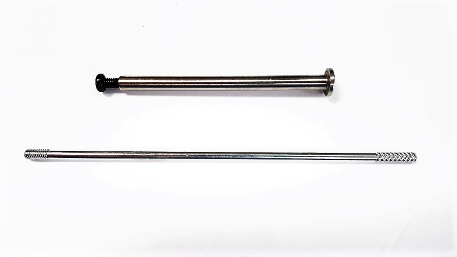
Stainless Steel Guide Rod and guide pin (no
spring) fits Gen 1 to Gen 3 Glock® 17, 19, 20 pistol**
Three models to choose from: G17; G19 or G20.
(This
one fit Gen 1 to Gen 3 Glocks. Need an adapter ring to fit Gen 4 Glocks)
Unlike the original Glock guide rods that are made of plastic, this stainless steel guide rod would not wear out or flex during shooting.
The first Glock Stainless Steel Guide Rod that has a
steel in to guide installation.
(no need to buy expensive installation tools)
Features:
1. Add weight to the front of
the pistol and helps reduce muzzle flip.
2. Improves shooting speed and accuracy
3. No chance of gun malfunction caused by broken plastic guide rod.
4. Can choose the best spring weight to match individual shooting style and ammo
type.
5. Requires no
modification of the pistol. Stainless Steel Guide Rod and guide pin - G
Specification:
1. Guide rods are CNC machined from stainless steel rod
2. G17 guide rod fits: 17,17L
22, 24, 31, 34, 35, 37
3. Rod weight with
screw: 0.57 oz (16.1 gm)
Total Weight with ISMI spring : 0.88 oz (24.8 gm) original: 0.38 oz (10.7 gm) –
a 130% increase in weight.
4. Overall length of stainless guide rod without screw attached:/ screw
attached: / ID marking.
US$13.50
G17 – 3.10” (78.7 mm)
/ 3.22” (81.7 mm) / G17 – no marking
on the plain end (big end) SKU 1375
G19 – 2.88” (73.3 mm) / 2.99” (76.1 mm) / G19
– one black line on the plain end (big end)
SKU 1373
G20 – 3.24” (82.3 mm) / 3.34” (84.8 mm) / G20
– one black cross on the plain end (big end)
SKU 1374
Installation: installation
video on youtube - Magloc Glock guide rod
*WARNING: Wear eye protection
and make sure the firearm is unloaded before installation begins. If
you are not
comfortable with the installation procedures described below, please have the
work done by a qualified gunsmith.
The following installation procedures can be viewed on youtube.
1. Separate the slide form the frame as per Glock
manual.
2. Separate
the recoil spring assembly as per Glock manual.
3. Screw the guide pin to the guide rod.
4. Slide the uncaptured recoil spring onto the guide pin.
5. Insert the whole assembly as a captured assembly as per Glock manual.
6. Detach the guide pin form the guide rod.
7. Attached the guide rod screw using a 3/32” (2.5mm) Allan key and Locktite.
8. Re install the frame as per Glock manual.
Warning: After
installation, test fire your pistol in various shooting position and making
sure that your pistol functions as expected.


Back to Front Page of
Smart Lock Technology Inc.